
Industries & Impact
Reverse-Engineering a Worn Casting From a Sample or 3D Scan
If you have a worn, broken, or obsolete cast part in front of you and no original drawings, you do not need them. We 3D-scan the part, rebuild a parametric CAD digital twin (restoring worn material from unworn reference geometry on the same part), identify the alloy in-house by spectrometry, and pour an ASTM-spec replacement from a patternless 3D-printed sand mold — typically 3–5 weeks end-to-end, no minimum order, no pattern tooling, USA-made.
Who this is for
This page is written for maintenance & reliability engineers, MRO planners, plant engineers, and procurement teams who have a worn or obsolete cast part in hand — a gearbox or bearing housing, pump casing or impeller, valve body, manifold, compressor cylinder head, wear part, drilling tool, marine engine component — and no original drawings, no CAD, and often no OEM left to call. If you need 1 to a few dozen replacements with real engineering paperwork (MTR, FAI, NDE), the rest of this page tells you how the reverse-engineering workflow runs and what to send us to start.
The short answer to the title question
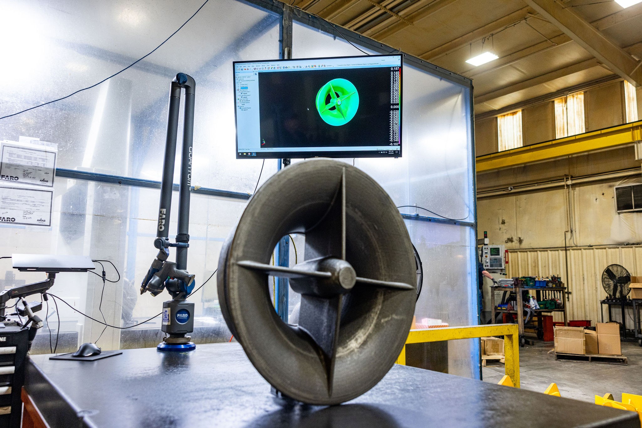
Yes, a worn cast part can be reverse-engineered into a manufacturable replacement without original drawings. The standard workflow is: scan the part (laser arm + structured-light for external surfaces, CT or destructive sectioning if internal geometry is unknown), rebuild a parametric CAD digital twin (restoring lost material from unworn reference geometry), identify the alloy by optical-emission spectrometry, verify tolerances via deviation analysis and FAI, and feed the model into a patternless 3D-printed sand mold for casting. End-to-end this typically runs 3–5 weeks rather than the 14–22 weeks of the traditional pattern-plus-pour path (Urick Foundry on production lead times).
Step 1 — Capture the geometry: picking the right scanning method
Which scanning technology to use depends on the part's size, geometry, surface condition, and whether internal features need to be captured. The choices we work in or arrange:
- Articulated laser arm (FARO-class)
- The workhorse for industrial cast parts up to a few feet across. Non-contact, dense point cloud of external surfaces (typical accuracy on the order of 50–100 µm). Best balance of speed, accuracy, and the ability to scan in awkward corners. Standard reference: FARO — 3D scanning efficiency in reverse engineering.
- Structured-light scanner
- Faster than laser arm on broad, smooth surfaces; sometimes better on shiny or low-contrast metal once a developer spray is applied. Good for housings, casings, and large flat features. See Creaform on 3D scanning for reverse engineering and QC of cast parts.
- CMM probing
- Slow for full-surface capture but the right tool for verifying critical features — bearing bores, hub diameters, flange flatness — after the CAD model is built. CMM also catches features the optical scanners miss in deep cavities.
- Industrial CT
- The only non-destructive way to capture internal geometry (water jackets, manifold cores, hidden passages) on a finished part. Limited by part size and density; we arrange CT through a bureau when the application requires it.
- Destructive sectioning
- When CT cannot resolve the internal geometry and a mating internal does not exist, one sample part is sectioned to capture the cavity profile directly. Cheap, fast, and definitive — but it costs you one part.
Most reverse-engineering jobs we see only need the external surface — gearbox and bearing housings, pump casings, valve bodies, wear parts — and the laser arm plus structured-light captures it in a day. Internal-geometry jobs add a step, not a roadblock.
Step 2 — From point cloud to a manufacturable CAD model
A raw scan is not a manufacturable model. It is millions of points. The work that earns the engineering paycheck is turning that point cloud into a parametric, feature-based CAD model a foundry can actually build a mold from — and a future engineer can edit when the next change comes.
- Mesh cleanup. Surface noise, scanner artifacts, and the worn / corroded patches are identified and isolated from the geometry that is "good as scanned." Software like Geomagic Design X or 3DReshaper is standard.
- Reference-surface identification. The unworn portions of the part — areas that did not see fluid, contact, or wear in service — become the reference geometry for the rebuild. Symmetry planes, bolt patterns, mating faces, and adjacent unworn features all anchor the as-new dimension.
- Restoration of worn material. Worn surfaces are extruded or re-faired up to the as-new condition: a wear pad rebuilt to its original height, a vane leading edge sharpened to its design profile, a seal face brought back to a flat plane. The reference geometry — not guesswork — drives the restoration.
- Parametric reconstruction. Bores, threads, flanges, bolt circles, and tapped holes are rebuilt as features in CAD with applied tolerances — not as static mesh surfaces. The model is "watertight" and ready for solidification simulation.
- Deviation analysis. The final CAD model is overlaid on the original scan and a color map shows where (and how much) the part wore. That deviation map is shipped with the part so the next time you scan a replacement after years of service you have a baseline to compare against — that is the digital-twin payoff (ATT Inc. — Professional 3D scanning reverse engineering services).
See our 3D Scanning & Digital Twin technical wiki for the underlying method we apply to every reverse-engineering job, and From Broken Part to Digital Blueprint for the broader workflow.
Step 3 — Recovering tolerances when the original drawing is gone
The hardest engineering judgment in reverse-engineering is tolerance recovery: how tight does this feature need to be when no print exists to tell us? Three rules govern the answer.
- Function decides, not the scan. A bearing bore is held to the bearing's required interference fit; a seal face is held to the seal manufacturer's flatness and finish call-outs; a mating flange is held to the bolt pattern and gasket compression of its mate. The application sets the tolerance, not what the worn part measures.
- General as-cast tolerances follow ISO 8062-3. For sand-cast iron and steel parts in the size class we typically pour, ISO 8062-3 DCTG 10–12 is realistic for non-machined surfaces — and that is what is called out on the released drawing. For finished features, ISO 2768 general tolerances or feature-specific limits are applied.
- Critical features get machined. We CNC-machine to print on our in-house equipment any feature that the application cannot tolerate in the as-cast condition — bores, bearing seats, sealing faces, key-ways, bolt patterns, register diameters. The released drawing comes out of the reverse-engineering step calling out exactly which surfaces are machined and to what.
The first piece off the new mold gets a First Article Inspection against the rebuilt model — dimensional verification on a CMM and against the mating assembly. If anything in the digital twin is off, we catch it on FAI, not on installation.
Step 4 — Identifying the alloy when the spec is unknown
If the part arrives with no material call-out, we identify the alloy before we pour. The standard methods:
- Optical-emission spectrometry (OES) in-house gives the full element-by-element chemistry of the parent metal. For an iron or steel casting, OES tells you not just "stainless" but which grade — CF8M, CF3M, A216 WCB, A536 65-45-12 — so the replacement can be poured to a named ASTM grade with documentation.
- Handheld X-ray fluorescence (XRF) is a useful field tool for first-look sorting but it sees only the surface and does not resolve carbon content — and on a worn cast part the surface is often the least representative material. We treat XRF as a triage step, not a final answer.
- Mechanical testing on a sister-casting tensile bar or on a sectioned specimen confirms hardness, tensile, yield, and elongation against the identified grade. For a one-off replacement going into a critical asset, the MTR on the new pour is the document the reliability team actually wants on file.
Alloy identification also opens the upgrade conversation. If the original was a brittle gray iron and the failure mode is cracking, the right replacement may be ductile iron. If the original was carbon steel and the service has shifted toward corrosive media, the right replacement may be stainless. See metals poured for the full alloy list we work in — gray iron, ductile iron, carbon steel, stainless, aluminum, with ASTM grades including A48, A536, A216, A351, A743, and B26.
Step 5 — From CAD to a poured patternless mold
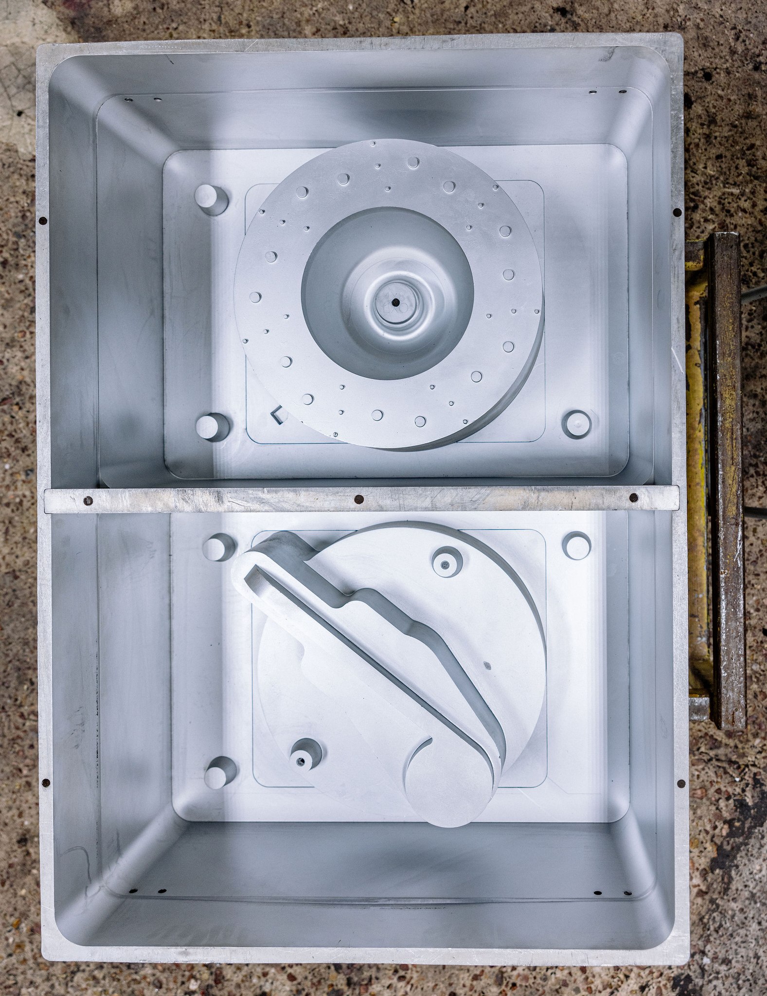
The reverse-engineered CAD model goes straight into our 3D sand-printing workflow: a binder-jet 3D printer prints the sand mold cope, drag, and cores directly from the CAD geometry. No metal pattern is built. No tooling cost is incurred. For non-patternless jobs — repeat-order short runs — the same model drives one of our four ABB robotic molders.
Before any sand is printed, the CAD model is run through solidification simulation in MAGMA / NovaCast. Hot spots, shrink risk, and feed paths are identified and the gating / risering is designed so the first pour is right. That step is invisible to the buyer but it is what separates "got a casting" from "got a sound casting." After pour, parts get heat treatment as the grade requires, CNC machining to print on the features that need it (see CNC machining), and NDE per the application — typically Liquid Penetrant (ASTM E165) on machined surfaces and Magnetic Particle (ASTM E709) on ferromagnetic grades. Final inspection runs against the reverse-engineered model and the FAI.
When NOT to reverse-engineer (and what to do instead)
Reverse-engineering is not always the right call. If you are in any of these situations, the answer is probably not "scan it":
- The OEM is still alive and quoting a reasonable lead time. Buy from the OEM. Reverse-engineering exists because the OEM is gone or the queue is unworkable, not as a default.
- The part is a high-volume commodity casting. If you need 5,000 a year of a standard part, a permanent pattern and a long-running mold is cheaper per piece than patternless. We are short-run specialists; we'll tell you when the volume calls for someone else.
- The part is so worn there is no recoverable reference geometry. If the entire part is corroded or eroded past the original surfaces — no unworn faces, no symmetry to anchor — the scan tells us how it failed, not what it was. In that case the right input is a less-worn sister part, an OEM photo or catalog cut, or measurements from the mating assembly.
- Hobby / decorative / unspecified projects. Reverse-engineering an engineering-grade casting is a real engineering exercise with real engineering paperwork. If the part has no specified function or material grade, this workflow is overkill and so is the cost.
What to send us to get a quote moving
The faster you can put these in front of us, the faster we can quote — and the more accurate the quote will be:
- The part. The worn or broken sample itself. Photos help us scope, but no photo replaces a scan of the actual part. If there are multiple worn examples (different stages of life), send them — they help bound the as-new geometry.
- The mating assembly or interfaces if available — shafts, bearings, gaskets, bolt-up flanges, seals — so the recovered tolerances are anchored to what the part has to mate with, not just what it once was.
- Service conditions. Fluid, temperature, pressure, speed, duty cycle, failure mode. This is what tells us whether the original alloy is the right replacement alloy.
- Any drawings, photos, catalog cuts, or OEM literature you do have, even partial. A 40-year-old microfiche is still data.
- Quantity — one is normal here — and whether repeat orders are likely.
- Acceptance — required NDE level, FAI / PPAP requirements, hydrostatic or pressure-test acceptance criteria if applicable, balance grade for rotating parts.
- Schedule. When do you actually need the part on a truck. Downtime jobs are flagged and run hot.
You can send it over here and we will come back with a path, a real schedule, and a price.
Related reading on this site
- The complete guide to legacy part replication — the pillar overview.
- Pump impeller replacement: cast from a worn sample — the rotating-equipment specific version.
- Replacing a discontinued pump or valve casting when the OEM is gone — the obsolete-OEM angle.
- From broken part to digital blueprint — the patternless recovery workflow.
- 3D scanning & digital twin technical wiki — the underlying scanning + reconstruction method.
- Legacy part replication — the full capability page.
Sources & standards
- ISO 8062-3 — Dimensional and geometrical tolerances for moulded parts (castings).
- ISO 2768 — General tolerances for linear and angular dimensions and geometric tolerances.
- ASTM E165 — Standard Practice for Liquid Penetrant Testing.
- ASTM E709 — Standard Guide for Magnetic Particle Testing.
- ASTM A48 — Gray Iron Castings.
- ASTM A536 — Ductile Iron Castings.
- ASTM A216 — Steel Castings, Carbon, Suitable for Fusion Welding, for High-Temperature Service.
- ASTM A351 — Castings, Austenitic, for Pressure-Containing Parts.
- ASTM A743 — Castings, Iron-Chromium, Iron-Chromium-Nickel, Corrosion-Resistant, for General Application.
- ASTM B26 — Aluminum-Alloy Sand Castings.
- FARO — 3D scanning efficiency in reverse engineering.
- Creaform — 3D scanning for reverse engineering and QC of cast parts.
- ATT Inc. — Professional 3D scanning reverse engineering services.
- Urick Foundry — Production lead times in the foundry industry.
- ScienceDirect — Case study on 3D scanning for reverse engineering of cast parts.
FAQ
Can you reverse-engineer a cast part with no original drawings at all?
Yes. The worn or broken part itself is the source of truth. We 3D-scan it (laser arm and/or structured-light), convert the point cloud to a parametric CAD model, restore worn material from unworn reference geometry on the same part, and use that model directly to print a patternless sand mold. Drawings are helpful but not required. If you do not have the part either — only photos and a few measurements — that is still workable but slower; send everything you have.
How is missing or worn material rebuilt in the CAD model?
We use the unworn reference geometry on the part itself to drive the restoration. Symmetry, mating surfaces, bolt patterns, and adjacent unworn features tell us what the as-new dimension was. The mesh is rebuilt as a parametric (feature-based) solid so threads, bores, flanges, and seal surfaces are real CAD features with applied tolerances — not a static surface scan. Deviation analysis (color map of scan-vs-model) confirms which dimensions are critical before we commit to the mold.
How do you handle the alloy when the original spec is unknown?
We identify the original alloy by optical-emission spectrometry (OES) in-house, then either match it or recommend a modern equivalent grade — sometimes an upgrade — based on the service. The replacement is poured to a named ASTM grade with a Material Test Report (MTR) on the heat so the chemistry and mechanicals are documented for the asset record.
What if the part has internal geometry — cores, water jackets, manifolds — that we can't see from outside?
Hidden internal geometry is the hard case. Options, in order: (1) industrial CT scanning if the part is small enough and you can route it to a CT bureau (we will help arrange); (2) destructive sectioning of one sample to capture the internal cavity directly; or (3) measurement from a mating part (the shaft, bearing, plug, or valve internal that sits in the cavity). Once the internals are captured, the patternless sand mold is built with the cores printed as part of the mold package.
How tight a tolerance can you actually recover from a worn part?
For as-cast surfaces, plan around ISO 8062-3 (typically DCTG 10–12 for parts in the size class we work in) — that is fine for the outside of the casting and non-mating surfaces. Critical features — bores, bearing seats, sealing faces, key-ways, bolt patterns — are CNC-machined to print on our in-house equipment, recovering tight tolerances ( ±0.001–0.005 in is routine on a finished feature, tighter on request). A First Article Inspection (FAI) on the first piece confirms the recovered model fits the application.
How long does the full scan → CAD → casting workflow take?
Many one-off, reverse-engineered replacements ship in 3–5 weeks: roughly 1 week for scan and CAD reconstruction, 1 week for solidification simulation and mold print, 1 week to pour and heat-treat, and 1–2 weeks for machining, NDE, FAI, and final inspection. Larger parts, internal cores, and heavier NDE / heat-treat routings push the longer end of that window. Downtime jobs are flagged and run hot — call before you ship.